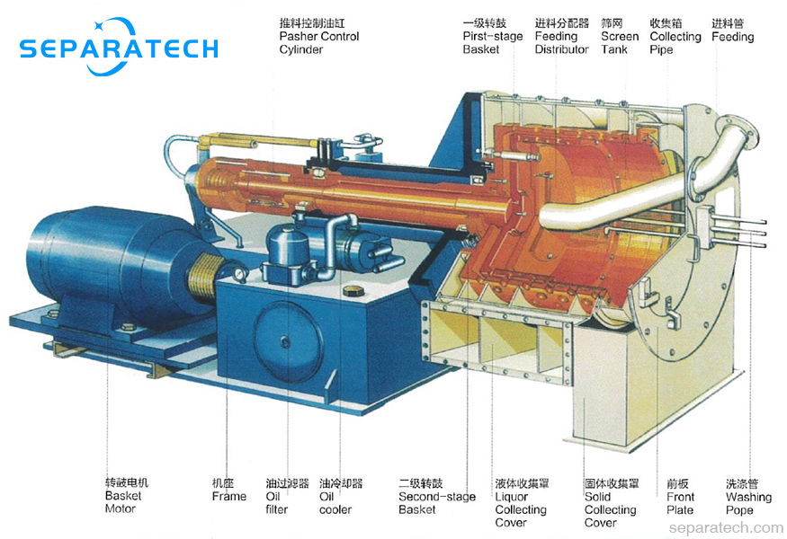
Pusher type centrifuge is a type of continuous filtration centrifuge that offers dewatering and washing materials continuously. it has been widely used for solids-liquid separation, such as relatively in-compressible feed solids, free-draining crystalline, polymers and fibrous substances.
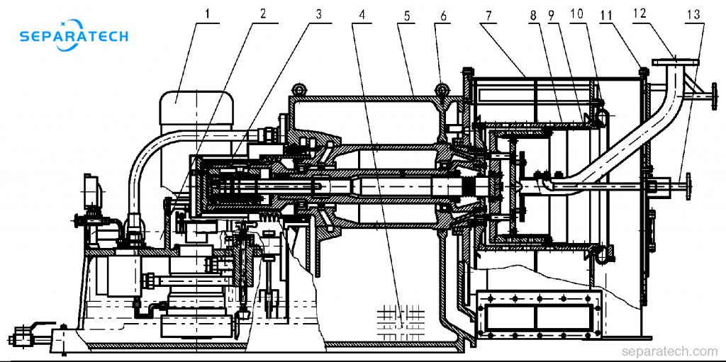
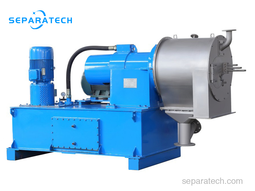
Main structure of pusher type centrifuge
1 Oil pump
2 Motor
3 Pushing mechanism
4 Oil cooler
5 Frame
6 Bearing housing
7 Hood
8 Bowl
9 Screen
10 Collection chute
11 Door cover
12 Feed tube
13 Wash tube
Pusher centrifuge working principle
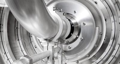
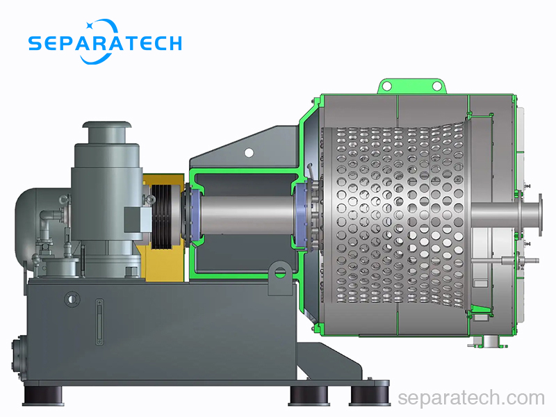
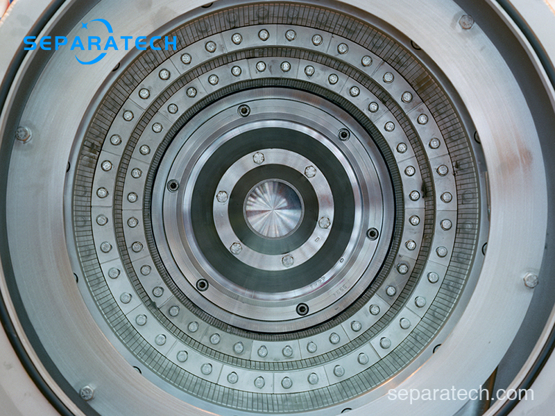
Two stage pusher centrifuge is continuously operating centrifuge. The product is fed through a feed pipe (or feed screw in the case of products that do not flow freely) into the feed distributor, which rotates with the basket. This accelerates the slurry and feeds it with uniform distribution to the feed zone, where the greater part of the liquid (approx. 80%) is filtered. In the feed zone, the solids grow to form a stable filter cake ring. The filter cake is conveyed in the direction of the solids discharge stroke by stroke due to the relative axial movement between pusher bottom and screen basket. During this process, an intact filter cake forms over the entire length of the screen. As the filter cake progresses from the feed zone to the solids discharge, it can be washed as required. For this purpose, a wash liquor is applied to the cake surface, displacing the suspension liquid and impurities. The solids are discharged at the end of the basket after each pusher movement.
A. Suspension inlet
The pusher type centrifuge is continuously fed with the suspension to be separated (solid-liquid mixture) via the inlet pipe. In case of poorly flowing products, the feed is effected via an inlet screw conveyor .
B. Suspension distributor
The distributor accelerates and distributes the suspension over the entire periphery of the sieves in the filling area of the first basket stage. SEPARATECH offers various application-specific distribution systems for even and gentle acceleration and distribution of the suspension.
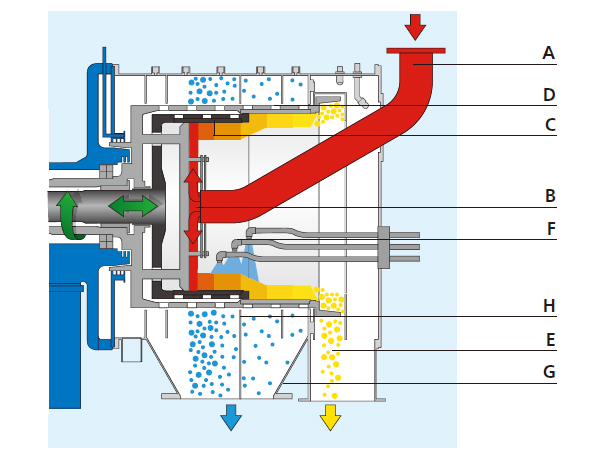
D. Second basket stage
The cake is pushed in annular sections by each pusher movement from the first to the second basket.
E. Solids discharge
After the second basket stage, the solids leave the pusher type centrifuge via the discharge track and the solids housing. Depending on the application, different discharge systems are used.
F. Product washing
If necessary, impurities in the mother liquor are washed out. The wash liquid is applied continuously over the cake via several adjustable wash nozzles.
G. Filtrate housing
The filtrate (filtered mother liquor and wash liquid) is collected in the filtrate housing and drawn off. Depending on the application, different filtrate housings and filtrate cyclones are used.
H. Filtrate separation
If necessary, the filtrate can be drawn off separately in each filtrate zone by means of separating plates fitted in the filtrate housing and disposed of or reused (e.g. counterflow washing).
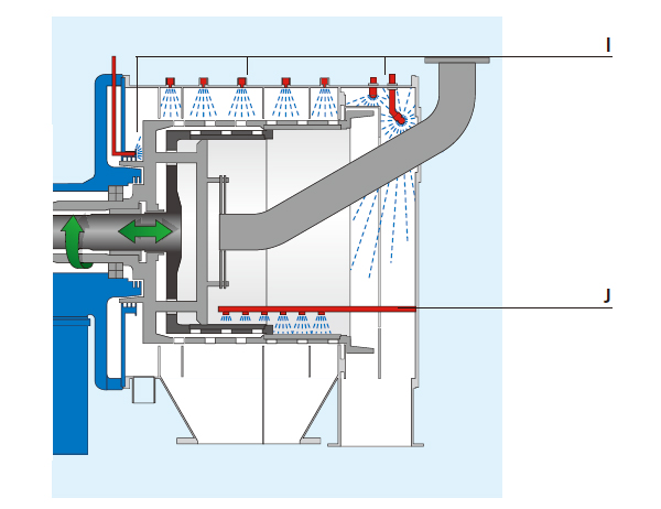
I./J. Flushing
The centrifuge process area is cleaned using flush liquid supplied through optimally arranged cleaning nozzles (I) and a clean pipe (J). Periodic flushing prevents the formation of crystals in the sieves and deposits in the solids housing.
Construction materials of pusher type centrifuge
• Austenitic steels
• Duplex steels
• Nickel-based alloys
• Titanium
Applications of pusher type centrifuge
High degree of adaptability of two stage pusher type centrifuge enables it can be successfully used in a wide product range, examples are:
ABS polymerisate
Adipic acid
Ammonium chloride
Ammonium hydrogen carbonate
Ammonium molybdate
Ammonium sulphate
Animal bone
Calcium nitrate
Calcium propionate
Chloride hydrate
Copper sulphate
Dicalcium phosphate
Ferrous sulphate
Fibrous materials
Flotation concentrate and residue
from the potassium industry
Foodstuffs applications
Glauber salt
Granulate
Hexamine
Lithium hydroxide
Melamine
Methacrylamide
Milk sugar
Nickel sulphate
Monoammonium phosphate
Pentaeritritol
Phosphate
Potassium chloride
Potassium nitrate
Potassium sulphate
Potash
Rape coarse grain
Seed grains
Silicone fluoride
Soda
Sodium acetate
Sodium chlorate
Sodium chloride
Sodium formiate
Sodium carbonate
Sodium nitrate
Sodium perborate
Sodium sulphate anhydride
Sorbic acid
Soya coarse grain
Tartaric acid
Various mixed salts
Zinc sulphate
Many more
| Designation | P200 | P400 | P500 | P630 | P800 | P1000 |
|---|---|---|---|---|---|---|
| Basket inner diameter (mm) | 200 | 400 | 500 | 630 | 800 | 1000 |
| Length of filteration area (mm) | 120 | 320 | 360 | 480 | 600 | 720 |
| Max. rotor speed (rpm) | 3000 | 2300 | 2000 | 1800 | 1600 | 950 |
| Max. G-force (g) | 1006 | 1180 | 1120 | 1140 | 1150 | 505 |
| Pushing strokes (mm) | 36 | 40 | 50 | 50 | 50 | 70 |
| Max. number of strokes (min-1) | 50-100 | 30-80 | 50-75 | 30-80 | 30-80 | 60-75 |
| Primary motor (Kw) | 3 | 7.5-15 | 30-55 | 45-75 | 55-90 | 90-110 |
| Oil pump motor (Kw) | 3 | 5.5 | 22 | 30 | 45 | 55 |
| Max. NaCl throughput (t/h) | 1 | 10 | 18 | 30 | 50 | 70 |
| Weight (Kg) | 800 | 2000 | 3500 | 4000 | 6000 | 11500 |
| Dimension L*W*H (mm) | 1650 X 1150 X 800 | 2550×1300×1155 | 3600×1500×1650 | 3150×1500×1400 | 3650×1900×1600 | 5250×2700×1950 |
